-40%
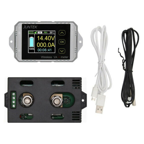
Wireless DC 0-400V 0-300A Voltage Current Watt Power Capacity LCD Combo Meter
$ 17.41
- Description
- Size Guide
Description
Wireless DC 0-400V 0-300A Voltage Current Watt Power Capacity LCD Combo MeterFeatures:
Brand new and high quality
It can measure voltage, current, power, charge and discharge capacity, watt-hour, time, temperature
It has over-current and over-voltage protection and limited protection and other protection functions
Detailed features as following
:
1. Chinese and English interface
2. Bidirectional detection
3. Touch button
4. Black and white display
5. One to many view
6. Safety protection
7. Accurate measurement
8. Power-off memony
9. Wireless transmission
10. Beautiful shell
Technical indicators:
Model
VAT-1030
VAT-1050
VAT-1100
VAT-1200
VAT-1300
VAT-4300
Voltage measurement range
0~100V
0~100V
0~100V
0~100V
0~100V
0~400V
Voltage resolution
0.01V
0.01V
0.01V
0.01V
0.01V
0.1V
Current measurement range
0~30A
0~50A
0~100A
0~200A
0~300A
0~300A
Current resolution
0.01A
0.01A
0.1A
0.1A
0.1A
0.1A
Relay
Internal
External
External
External
External
External
(optional)
(optional)
(optional)
(optional)
(optional)
Temperature measurement range: -20~120℃
Capacity display range: 0%~100%
Power measurement range: 0~200kW
Power resolution: 0.001W
AH measurement range: 0~2000kAH
Capacity resolution: 0.001AH
Watt-hour measurement range: 0~4000kWH
Watt-hour accuracy: 0.001WH
Time measurement range: 0~99 days
Time resolution: 1 second
Communication channel range: A~Z (26 channels)
Communication channel range: 01~99
Voltage accuracy:
±
2%+3 words
Current accuracy:
±
5% + 10 words
Sampling rate: 5 times / second
Communication distance: up to 10 meters (32ft)
Measurement module power consumption: About 0.4W
Display module power consumption: 0.5W
NCP: 0~300A(negative over-current protection setting)
OCP: 0~300A(positive over-current protection setting)
OVP: 0~100V(over-voltage protection setting)
LVP: 0~100V(under-voltage protectioin setting)
Protection delay time: 0~10s
Power wiring diagram
The instrument can be "wired communication" and "wireless communication"
1. Display power supply wiring diagram is as follows:
When the display board is powered separately, there are two power supply interfaces, which are the USB
5V power supply interface and the 2P socket interface(8-16V) power supply
2. Measurement module wiring diagram is as follows:
2.1 VAT 1030 wiring diagram:
The wiring method on the left is applicable to the discharge measurement of the battery and the measurement of the DC circuit,
the wiring method on the right is only applicable to the charge meaurement of the battery
2.2, wiring diagram of VAT1050,VAT1100,VAT1200,VAT1300 measuring voltage is 10-100V:
The above figure applies to VAT1050,VAT1100,VAT1200,VAT1300 measurement circuit of 10-100V;
attention at this time attention to the jumper cap to receive 2W, the left wiring method is suitable for
battery discharge measurement and DC circuit measurement; The wiring method on the right is only
suitable for charging the battery
2.3 VAT4300 measurement voltage is 0-400V and VAT1050,VAT1100,VAT1200,VAT1300 measurement
voltage is 0-100V wiring diagram:
The figure above applies to batteries or circuits where the VAT4300 measures 0-400V and VAT1030,
VAT1100,VAT1200 and VAT1300 to 0-100V at this time,note that the jumper cap must be connected
to 3W and need to use a 10-30V. The DC voltage supplies power to the measurement module; the wiring
method on the left is suitable for the discharge measurement of the battery and the measurement of the
DC circuit; the wiring method on the right is only suitable for the charge measurement of the battery
2.4 VAT1050,VAT1100,VAT1200,VAT1300 and VAT4300 external relay wiring diagram
The wiring method on the left is applicable to the discharge measurement of the battery and
the measurement of the DC circuit; the wiring method on the right is only applicable to the
charge measurement of the battery. When selecting the relay,pay attention to the relay's contact
can withstand the maximum current in the circuit,such as the current in the test current is 80A,
then select the relay,you must select the contact current can withstand 100A relay, the relay supply
voltage can choose 12V or 24V when the 12V relay is selected, the external power supply voltage
must be set to 12V, which is the same as the relay supply voltage


