-40%
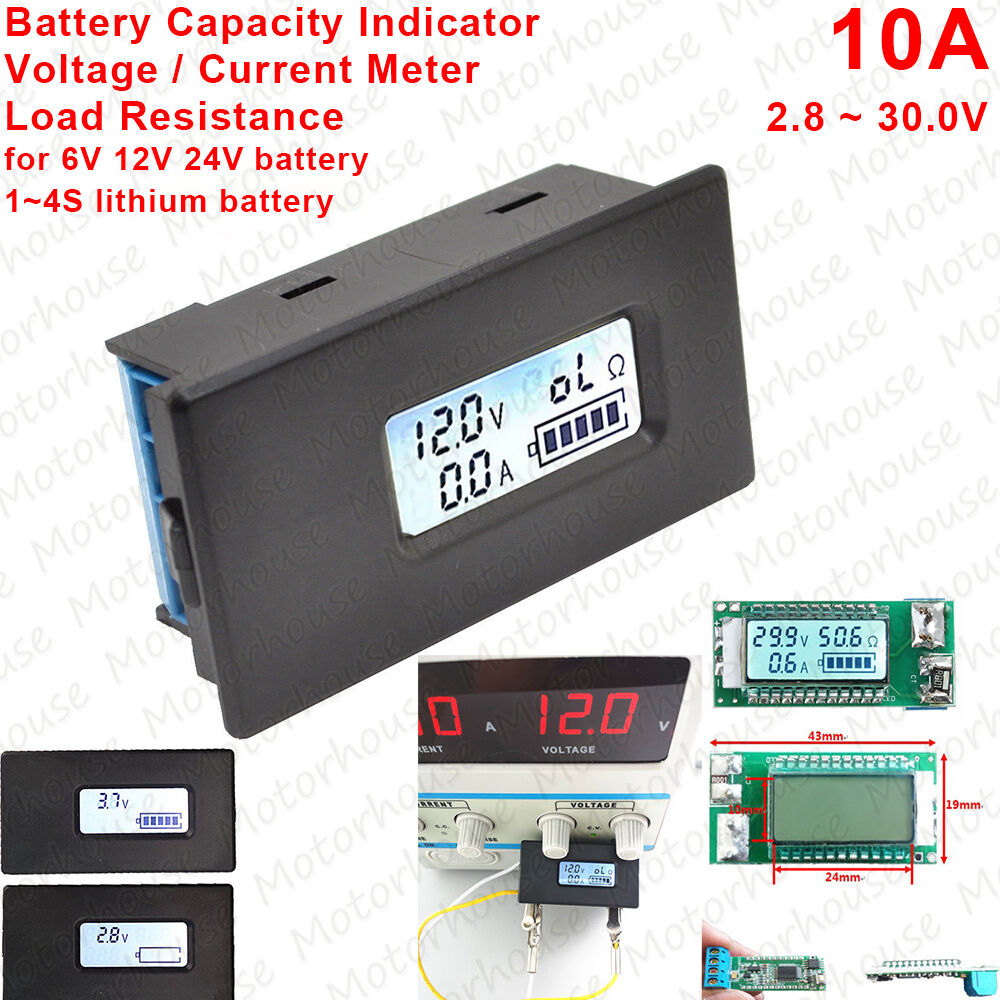
Capacity Indicator Voltage Current LCD Meter For 12V 24V Lithium Li-ion Battery
$ 3.44
- Description
- Size Guide
Description
Welcome to efans_studioYou may also like, welcome use "Add to basket to buy"
Description
Welcome to our store:
efans_studio
Tips:
If you need Large quantity, please contact us, we can wholesales.
Specification
:
A.
Function
1.
Electrical parameter measurement(voltage, current, load resistance, dump energy(symbol display))
2.
Backlight(you can control the backlight on/off through the button)
3.
LCD display(display voltage, current, resistance, energy at the same time)
B.
Display and Button
1.
Display interface
LCD display voltage, current, resistance, energy at the same time
2.
Display format
2.1
Voltage: display the current input voltage
Indication range:
2.8
~
30.0V
2.2
Current: display the current load working current
Indication range:
0.0
~
10.0A
2.3
Resistance: display the current load resistance
Indication range:
0
~
999Ω
R
<
10Ω display 0.01
~
9.99Ω
10
Ω
≤R
<
100Ω display 10.0
~
99.9Ω
100
Ω
≤R
<
1000Ω display 100
Ω
≤R
<
1000Ω
1000
Ω
≤R display “oL”Ω
2.4
Energy: display the current battery dump energy
Battery level is shown through the five battery level grids on the LCD screen, is distinguished by the current voltage and cut-off voltage and full-scale voltage. So before test, you should set the cut-off and full-scale voltage.
Every grid stand for 20% energy, At full-scale voltage, it displays 5 grids, when comes the battery cut-off voltage it will display format 0 and so on.
3.
Button
3.1
Backlight control
The backlight turn off acquiescently when power on, you can turn it on or off by short press the “set” button.
3.2 Cut-off voltage of the battery and full-scale voltage settings
Step 1:Long press the“SET” button for 3 seconds to enter the battery cut-off voltage and full-scale voltage setting state, then release the button;
Step 2: After entering the state, voltage area flash to display the current battery cut-off voltage
,
and use the zero battery level symbol to indicate it is the cut-off voltage setting state; then you can shot press the button to add one, long press the button can add one quickly; the range of cut-off voltage setting is 2.8 ~ 29.9V, but not more than the full-scale voltage.
Step 3: When there is no key operation more than 3 seconds, it automatically enter into the full-scale voltage setting state;
Step 4: After entering this state, voltage area flash to display the current full battery level voltage, and use the full battery level symbol to indicate it is the full-scale voltage settings state; setting method is as same as the cut-off voltage; the range is 2.8V ~ 29.9V, but not less than the cut-off voltage.
Step 5: When there is no key operation more than 3 seconds, it will automatically save, if there is no error after saving it will quit
automatically, if the value is incorrect or save incorrectly, it will display “Err SAu” for 1 second, and exit.
C.
Discharge resistance
Many user like to use resistance as a load to do the battery discharge test, there is no stipulation of the resistance value and power, you can calculate through the formula:
The value of discharge resistance=Voltage/current
The power of discharge resistance=Voltage* current
D.
Calibration
The product may be has the measure data inaccuracy or in a mess because of the interference, faulty operation or wrong wiring and so on, then you should calibrate it. The method is as following:( if you don’t have the calibration equipment or your calibration is failing, please contact your supplier)
Step 1: Cut off the power, open the back cover, short circuit the calibration point( there are two holes marked “W” on the margin of the circuit board)
Step 2: Then give it the standard voltage and current for10v/1A( for example: use the DC electrical source to output 10V voltage to the product, and the load wire a standard resistor of 10
Ω
/10W, then you can get the calibration condition.)
Step 3: Then the screen will display
“10V,1A”
flickeringly, which indicate it is the calibration state and the calibration condition is “10V,1A”
Step 4: If the calibration is successful, the screen will display “PASS” for 1 second, then exit the calibration state and return to normal, if display other information, it means the calibration is failing.
Step 5: After calibration, cut off the power and calibration point, then you can use it normally.
E.
Note:
1. This module is suitable for indoor, please do not use outdoor.
2. Applied load should not exceed the rated voltage, current.
3. Wiring order can’t be wrong.
F. Specification Parameters
1. Working voltage: 2.8
~
30VDC
2. Test voltage:2.8
~
30VDC
3. Rated power: 10A
4. Measurement accuracy: 2%
G. Wiring diagram
H. Dimension diagram (mm)
Payment
We only accept payment via Paypal.
The buyer is responsible for any applicable import duties and local taxes.
Usually there's no any charges for small parcel. But please verify with your customs before making your purchase.
Delivery details
The items will be shipped within 1~2 working days after your payment is received and cleared.(excluding Saturday, Sunday & Holiday)
All items will be shipped to your Paypal address, so please make sure to provide us with the correct, precise, detailed shipping address.
The Delivered time to USA buyer is about 7~20 days, other country about
15~35
days delivered.
Notes: pls contact us if you need need trackable or express shipping service.
Terms of sales
All the items will be tested before shipping. Buy them with the confidence!
We maintain the excellent service standards
and strive for 100% customer satisfaction and
Positive feedback.
If you have any problem, please do feel free to contact us before leave Neutral
or Negative
feedback, so that we can satisfactorily address your concerns.
Return
We afford all cost if it's our fault. Exchange or refund.
Contact us
We strive to provide you with the best service, reply your question within 24 hours.
Business time:
9:30~21:30 (GMT+8)
exclude the weekend and holidays.
Contact us


